Sunday, December 26, 2010

Cabin Frame

The frame for the windscreen and cabin deck (or roof?) is under construction. The windscreen and cabin deck are both cambered or curved, so all of the frame pieces have to be sawed out from larger pieces of lumber in a curved shape. The windscreen base is glued and screwed directly to the fore deck.

The cabin deck frame members are glued and screwed to the cabin carlines. The front frame member is a bit tricky, because it has to match the curve of the cabin deck and the curve of the windscreen. To accomplish this, the front frame member is cut out with a slightly larger curve than the others and installed at an angle. All of the frame members were roughly cut, then installed on the boat. Then they are trimmed to shape. So the lumber cutting didn't require a lot of precision and isn't as complicated as it looks.

After the frame members are installed, the top-centers of them are notched and a king plank of 1/4 inch plywood is installed. The king plank stiffens up the structure considerably.


The shape of the cabin is starting to become apparent.


The windscreen plywood is ready to be installed. Then, I'll finish the back part of the cabin frame, which will include a cutout for the companionway hatch.

I have some extra time to work on the boat during the holidays, so I'm hoping to get a lot done in the next week or so. I'll keep you posted.

Tuesday, November 2, 2010

Foredeck and Cabin Sides

The foredeck and side decks along the cabin have been installed. These are glued and nailed to the frame members.


The cabin sides have been made and installed. I modified the design to make the cabin sides and the cockpit coamings all one piece. I cut out a cardboard pattern first to avoid mistakes, then cut out the plywood. This helped me get the bottom curve right.

The pic below shows the cabin carlines being glued and nailed to the cabin sides. You can see some scrap pieces of 2x4 that have been cut to a curve and clamped to the assembly. This will make the curve of the top of the cabin side is the same as the bottom.

Here are the cabin sides all glued and nailed to the boat. I checked the angles to make sure everything looked right before the glue dried. One side was at a different angle than the other, so some ropes and clamps were added to hold everything in the right spot while the glue dried.

These window openings will later be sealed water-tight with acrylic windows.

Here's a better pic of the scrap 2x4 pieces that will later be removed. If you look close, you can also see a small slot in the side deck. This will be for a metal strap called a chainplate to pass through. The chainplate is where the standing rigging wire attaches to the hull. (more on that when I install the chainplates).


The next step is to install the frame members of the cabin roof and then install the cabin roof and cabin front. This will be a very similar process to the foredeck construction.

Saturday, September 11, 2010

Side and Aft Decks Glued and Nailed

The boat spent some time on the front lawn this weekend so I could pick up some plywood with the trailer. All the granny knots made when tying down the plywood reminds me that I need to learn how to tie knots before I go sailing for the first time. But I got the plywood home without it flying off and the trailer works great, besides being a bit bouncy without a boat on it.


The aft and side decks have been glued and nailed down. Before I glued the side decks on, I attached some pieces of Doug Fir to decks (nailing from underneath). These are the bases for the coamings. As you can see, the coamings are going to be curved nicely.

The holes in transom are also shown in the pic above. The top hole is a drainage hole for the motor well. The middle two are drainage holes for the cockpit. These holes may or may not be above the waterline, so I may need to plug them when sailing ... we'll see. The lower holes are drainage holes for the bilge, which will be plugged when the boat is in the water.

The boat is now safely in the garage again. In the photo below, you can see some notches in the coaming base pieces. This is for drainage, so water will not pool on the side decks along the coamings.

Here's a closer shot of the motor well. Just a watertight plywood box. The bottom is sloped toward the drainage hole. I still need to put a little oak cap along the back edge and round the edges a little.

I also glued and nailed the cockpit sole (floor). I cut some round holes in the floor for access to the back section of the bilge. These holes will be fitted with plastic watertight hatch covers.

Sunday, August 8, 2010

Cabin Bunks and Cutting Out Plywood

The frames for the cabin bunks have been made. Here is the fore-side of the bulkhead with some frame members added. I made the top piece out of white oak, since I figured I'd be kicking it a lot climbing in and out of the cabin.


All of the bunk frame pieces are screwed and/or glued into notches in the hull frames. They will strengthen up the structure of the hull as well as provide a flat surface to sleep on in the coffin-sized cabin. I still need to add a few more pieces around the centerplate trunk. I'm going to wait to do that until after the cabin framing is done and I'm ready to install the mast compression posts.


The bunk plywood is a strange shape that is impossible to measure without a pattern. This is my pattern made from scrap cardboard.


And here are the resulting bunk plywood pieces made using the cardboard pattern. The two plywood pieces are slightly different, since the boat isn't perfectly symmetrical. Good thing I checked that before I cut out both of them. This plywood is going to be removable (not glued down), since I want to be able to check the area underneath for debris or rot and also use that space for storage or flotation foam.


Also, there are some removable plywood floors inside the cabin on either side of the centerplate trunk.


I was curious if I had enough plywood, so I cut out a lot of the plywood pieces I will be needing later. Here are all the rudder pieces cutout and waiting to be glued together. The rudder is a hinging "kick-up" type.


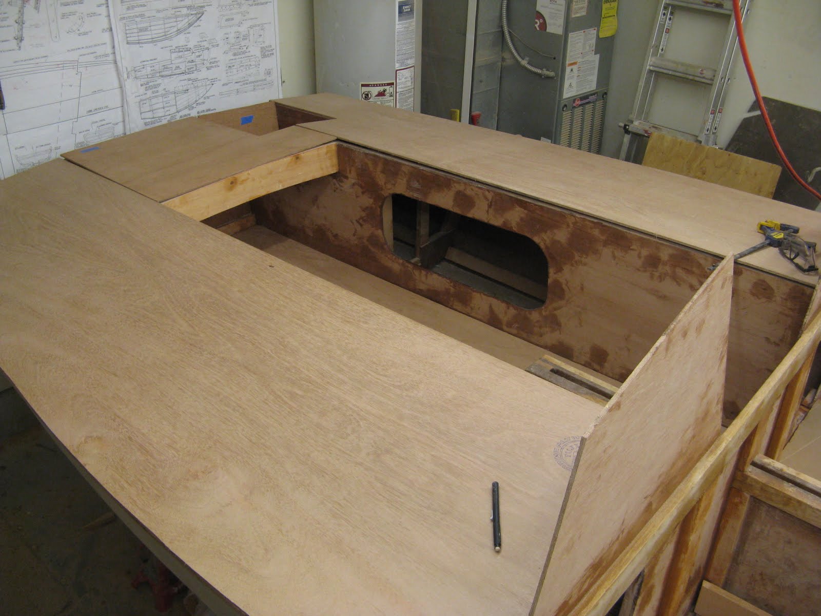
Also I cut out the aft, side, and fore deck pieces as well as the cockpit sole (floor). All of these pieces will eventually be glued and nailed down, but they are not attached to the hull yet in these pictures. Yes, even the cockpit sole will be glued down, but with a few round waterproof access ports to inspect the bilge underneath. (Remember, I'm modifying the design to make a water-tight cockpit).


Finally I got a lucky break ... the side deck plywood pieces were JUST narrow enough to loft onto one sheet of plywood, creating very little waste. I didn't plan for that when modifying the design and widening them, but fortunately I didn't make them a half an inch wider.

Also, I faired the tops of all the deck frames to the proper camber, as you can kinda see in this pic.


I figure I need two more sheets of plywood to finish the deck and make the cabin. That purchase can wait a week or two though. Next I'm going to clean up, sand, and paint the bilge, since that will be easier to do before the decks are installed. This doesn't seem like the most fun task of boat building, but it's gotta be done.

Tuesday, July 6, 2010

Cockpit Framing

Well, it has been a year since I've started building the boat. A more ambitious or experienced builder may have been almost done by now. I'm working on the boat casually after work and on weekends. In the beginning, I often spent more time scratching my head looking at the plans than actually constructing something. And I took about two months off. Also, I'm trying to do everything myself, including rigging and sail assembly, which takes some extra time. Anyway, the boat is now over-budget and behind schedule ... not surprising for a project run by an engineer!

I made some good progress over the holiday weekend. The cockpit framing is almost done. There is nothing particularly difficult with this process ... just cut to length and make notches in the frames where necessary, then glue and screw.


All of this framing is going to be covered with a plywood deck. Well, everything except for the motor well, which is the small square opening (the far one with plywood sides, near the transom) in the picture below.


I had to modify the side deck frames to make the side decks (which are also where you are supposed to sit) wider, since I didn't notice how narrow the seats were until we flipped the boat over. These modifications weren't as difficult as I feared, but in hindsight I should have made this change in the beginning. I also installed a small stringer down the middle of the seats, so the side decks won't flex when I sit or stand on them.


I decided to cover the sides of the the foot well with plywood to make a water-tight cockpit, which isn't in the original plans. There are hatch openings in this plywood to access the storage areas under the side decks. I plan to make some water-tight plywood hatches to cover these openings. So any water flooding into the cockpit won't get into the bilge or cabin.


I also made some cutouts in the bulkhead to access the area under the side decks from inside the cabin ... and for better airflow inside the boat, which helps prevent wood rot.


I'm changing the design of the motor well too. I want some sort of motor well, since without one, an expensive bracket would be required to attach an outboard motor. (I can't afford a motor at the moment and I'm not sure if I will ever get one, but I'm building a motor well just in case.) Instead of the large motor well shown in the plans, I'm making a much smaller one off to the port side. Since I made the foot well so narrow, the motor well framing must be a little more complicated. I'm kinda just making it up as I go and it's all fitting together ok. (The following picture is looking down on the motor well framing. The plywood bottom of the motor well isn't installed yet.)


It all looks a little sloppily constructed, but the tops of all of these frames will later be planed fair and shaped so that the plywood decks will fit up nicely.

Friday, June 11, 2010

Bulkhead and nail strip

The bulkhead has been installed. A pattern was made of scrap pieces using a hot glue gun. The pattern was then removed from the boat and traced onto plywood.


The shape of the cabin and the companionway are also drawn and then the bulkhead is cutout. The bulkhead is two pieces so that it fits around the centerplate trunk. The bulkhead plywood is simply glued and nailed to the back of frame #4. There is a seam in the middle that is reinforced with a short 3/4" x 2-3/4" piece of wood, epoxied and screwed. While the glue was setting, I braced the bulkhead with 2x4's so that the two sides of the bulkhead would align.


With the plywood in place, I can start drawing on it and attaching the frame to it. Here is the frame that attaches the cockpit sole and side decks to the bulkhead. It's also epoxied and nailed in place. Other frame members will fit into the notches in these pieces.


If you compare the above photo with the Hartley plans below, you can really see how I'm starting to diverge from the plans. The side decks in my boat are much wider and the companionway is going to be a traditional (albeit small) drop board style. I'm going to make a small hatch on the cabin roof too, so hopefully it will be possible to egress that small companionway.


A 3/4" thick nail strip (Doug Fir) is glued and screwed along the sheer of the boat. Keeping glue from running down the side of the boat was difficult, but a piece of masking tape really helped keep it clean. The strip of wood broke the first time, so I had to re-scarf it and try again.


The deck plywood will later be nailed to this nail strip. I chose Doug Fir since it's easy to nail into and doesn't split. After the deck is attached, I'll cap this piece with a 1/2" thick piece of white oak for protection.

I tapered the nail strip slightly toward the bow, since I think it would have looked kinda "clunky" if I didn't.


By the way, sorry for the LONG lapse in the blog postings. I was taking a break and doing some household projects. I realized that I'm not going to get the boat done in time for this summer, so I might as well slow down and enjoy the construction more. For example, here's a composter and a cedar planter box I made while taking a break from the boat.


Notice that I used the old boat trailer hubs and a galvanized pipe for the composter axel. :)

The boat building blog posts will now commence again, bi-monthly probably.

Monday, April 19, 2010

Foredeck Beams

I'm starting the long process of framing the interior of the boat.

The curved foredeck beams have been cutout and installed. The pattern for each is given in the plans. The plans didn't say how to attach them exactly, so I just glued and screwed them to the side of the frames and the inside of the gunwale. I made a small notch in the gunwale for the deck beams in between the frames to make it easier to screw on. Also, a strip of 3/8"x3" plywood called a king plank is checked into the top center of the foredeck beams.


Then I carefully trimmed the gunwale shear line to align with the frames and deck beams. (I used a circular saw which is actually an accurate trimming tool that's faster than a hand plane if you have to cut off a lot of material.) The plywood deck will be attached to the frames and the gunwale. They all have to align with no gaps.

Two carlines are also installed aft of the foredeck beams. These match the curve of the gunwales, but are angled inboard, as you can see in the pics below. They are angled this way because the cabin sides are going to be secured to the side of these carlines and the cabin sides are angled.


Here's a good pic of the connection of the cabin beam, gunwale and carline. You can see the cabin beam slightly checked into the gunwale (not too much so to not weaken the gunwale). Some people prefer not to check into the gunwale at all, but I found it easier to assemble this way. Also you can see a funny shaped spacer block that the carline is secured to.


Bending these carlines into position was unexpectedly very difficult. It required a compound bend in two directions. After breaking the first one, I cut out a piece that was slightly curved downward (about 1/2") in the middle, eliminating the need for a compound bend. This doesn't sound like much of a difference, but it significantly decreased the force required to bend the carline into position.


On an unrelated topic, I made a new scarfing jig. If you recall from almost a year ago, I made a scarfing jig to use with a belt sander (which is almost comical to think about now). Here is the new one that works with my table saw. It just keeps the piece being cut at a 12:1 angle. It couldn't be simpler really. I've been using it instead of the belt sander jig and I thought I would show it on the blog just to be thorough. I'm going to need it again soon to make the shear capping pieces.

Sunday, April 18, 2010

Jib Sail Finished

I finished the jib sail. Here is a pic of it being folded up for storage. Notice all the jib snaps installed and the leather sewn on the corners. (Never mind the dog grazing on sewing scraps.)


I also made three duffel bags for the three sails following purchased plans. The duffel bags are made of nylon and pretty easy to sew. Making all three of them took me about 5 hours. The piece of fabric is folded in half and sewn together, then the bottom is cleverly folded to make a square and sewn down. The bag is then just turned right side out. There is also a draw string pocket along the top. The jib sail is in one of the bags in the pic, but the other two are empty waiting for me to make the other two sails.


But the "sail loft" is now cleaned up and mothballed for now. I just wanted to make sure that the sailmaking wasn't going to cause me any problems and it isn't. I'm going to get back to working on the hull now.


I apologize if the sail assembly portion of my blog isn't very detailed. If you want to learn more about the sail kit assembly, I figure you can just go to the sail maker's website and watch streaming videos. I just want to share my personal experiences like:
- yes, I can sew sails with a crappy home sewing machine.
- making a sail pattern before sail assembly for future use.
- details about my specific sails, etc.

Wednesday, April 7, 2010

Working jib sail almost complete

I almost finished sewing the working jib sail.

My first stitches are ugly ... but they are slowly getting better. I spent about 4 hours learning how to use the sewing machine and adjusting it using some scrap fabric. After a lot of "bird nests", I got it under control. But then when I started sewing the sails, I had a whole new set of problems. The hardest part is feeding the large pieces of fabric through the machine and keeping the stitch straight and evenly spaced. Having an uneven stitch just looks a little funky and doesn't seem to affect the seam's strength too much, so I'm not too worried about it. (Luckily the sail maker sold me white thread that matches the white fabric, so sewing mistakes are not too conspicuous).

The sailmaker sold me a bunch of double-sided basting tape. Sewing the sails would be impossible without this stuff. Even the pros use it. I basically just tape everything together before sewing and then nothing moves when it goes through the sewing machine. The tape just stays hidden in the seam permanently after sewing.

My cheap little machine sews through very many layers of material surprisingly well. At one corner of the sail, I sewed through 8 layers of 4.4oz sail cloth and two layers of thick webbing.

So here's a little description of how this sail is constructed. The horizontal sail panels are sewn together with a 5/8" overlap seam with two rows of zig-zag stitches. The corners are reinforced with 4 layers of additional fabric patches. Here is a couple of pics after the panels and corner patches were sewn together, but before the edges and corner hardware are done.


At each corner there is an attachment point for halyards and sheets (ropes). One corner has a D-ring. The D-ring is attached to the sail with multiple pieces of webbing that are sewed onto the corner patches. The other two corners have wire thimbles. The thimbles are attached to a wire that sewn into the luff edge of the sail (kinda like pipping on upholstery). Each of these attachment points is heavily reinforced with thick twine that is hand sewn. The thimbles are further reinforced by a brass ring that's sewn into the sail next to it, then twine secures them together.

All the hand sewing is done with very heavy sailmaker twine. The hand sewing was pretty easy since I used an awl to pre-poke the holes and a coin to push the needle through. The corners are dressed with little pieces of leather, which is just there to prevent chafing. Here's some pics of the wire thimbles and wire sewn into the sail. (The leather is partially sewn on at the moment.)


Bronze jib snaps are attached behind the steel wire all along the luff edge to attach the sail to the fore-stay wire on the boat. You can see one of these snaps installed in one of the pics above. Without this wire in the sail, the grommets that the jib snaps attach to would just rip out of edge of the sail.

The other edges (the foot and leech) are just double-hemmed.

So I just have to finish stitching on the leather patches and then I'll have a perfectly functional jib sail (with some comically ugly stitches in a few spots ... but oh well).