Monday, February 14, 2011

Spar Making - Part 1

I've started making the mast and boom. They are going to be made of Douglas Fir wood. I debated between wood and the (infinitely more popular) purchased hollow aluminum extrusion. I decided on a wooden mast because it's slightly cheaper, has more character, and, most importantly, fits with the whole spirit of this do-it-yourself project.

The mast is going to be hollow box-section and the boom is going to be a solid rectangular section. Here is the cross-section of the mast from the plans.

The boom is about 9 feet long and the mast is about 18 feet long (just a few inches shorter than the garage). The lumber I purchased is only 12 feet long, so I need to scarf together pieces for the mast.

The pic below shows all the douglas fir pieces of the mast and boom cutout and ready to be glued together. The pieces on the right are for the boom. The longer pieces on the left are for the mast. An important detail to notice is that all of the scarf joints are staggered, so that they will not be all in one spot of the mast. This makes the mast stronger. (Also shown in the middle of the pic are some oak pieces that will be the rub rail along the shear line of the boat ... not related to the spars.)

This took me an entire Sunday, because all of the pieces had to be ripped (cut lengthwise) and then planed (shaved down to the correct thickness). Then the diagonal scarf joints had to be cut for all the mast pieces. A table saw and a bench planer are pretty much mandatory tools for these tasks.

I've also started making the mast step. The mast step is where the base of the mast rests on the boat. There can be large forces traveling through this joint, so it need to be built stout.


The mast step in the plans doesn't seem quite strong enough to me, so I've decided to beef it up a little. Here is a pic showing the side of my mast step (left) compared to the one shown in the plans (right). I'm also going to secure everything with big screws and lots of epoxy.

On this boat, the mast step performs another function, which is to support the mast while the boat is being trailered. So the spacer block of the mast step should be angled on top to match the angle of the mast in the trailered position, as shown in the pic below.


Here is a pic of the mast step during the initial dry fit, just before gluing.

Tuesday, February 1, 2011

Companionway Frame

The excess plywood of the cabin deck is trimmed with a hand saw and then sanded flush with a belt sander.


The frame around the companionway opening is screwed and glued in place. The plywood is sandwiched between two pieces of frame, making a slot for the companionway drop board (or removable door) to secure in. The two holes on the lower horizontal frame piece are for drainage.


The companionway drop board (a piece of plywood cut to shape) is being trimmed to fit the opening. Since the sides of the opening are at an angle, the door only has to be lifted about 4 inches to remove from the opening. I plan to make a top hatch that fits over and around the drop board, so that it should be fairly water tight. I will probably put a little circular window in the drop board too.


I've also been sewing the large main sail together.

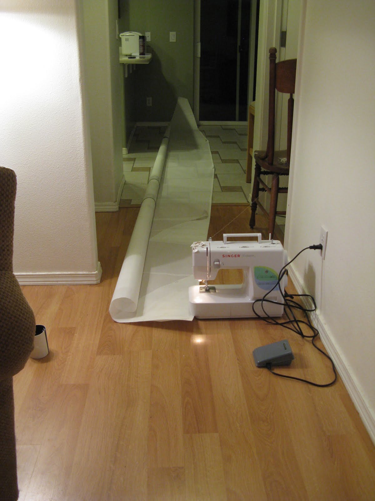
However, we had to move outside of the small spare room into the longest hallway of the house. I needed enough room to fit the rolled up sail on either side of the sewing machine when doing long seams.

Here is a homemade sail-making tool that I can't live without: a short length of plastic drain pipe cut down the middle. This makes a great clamp to keep the sail rolled up.


I'm almost done with the mainsail and I haven't gone into too much detail about it on this blog. Part of the problem is that the sail is always rolled up, so it would be difficult for you to tell what the pictures were trying to show. So I'll show more details about the sail when I can unroll it and run it up the mast. For now, it'll stay rolled up in the spare room.

Tuesday, January 4, 2011

Cabin Deck

The cabin frames are now finished. The companionway opening to the small cabin is now starting to take shape. Like I discussed in a previous post, this opening has been modified from the original plans to make the boat more safe in my opinion.

The windscreen plywood has been installed and trimmed to shape. Sailboats were kinda funny looking to me at first, not having a see-through windshield.


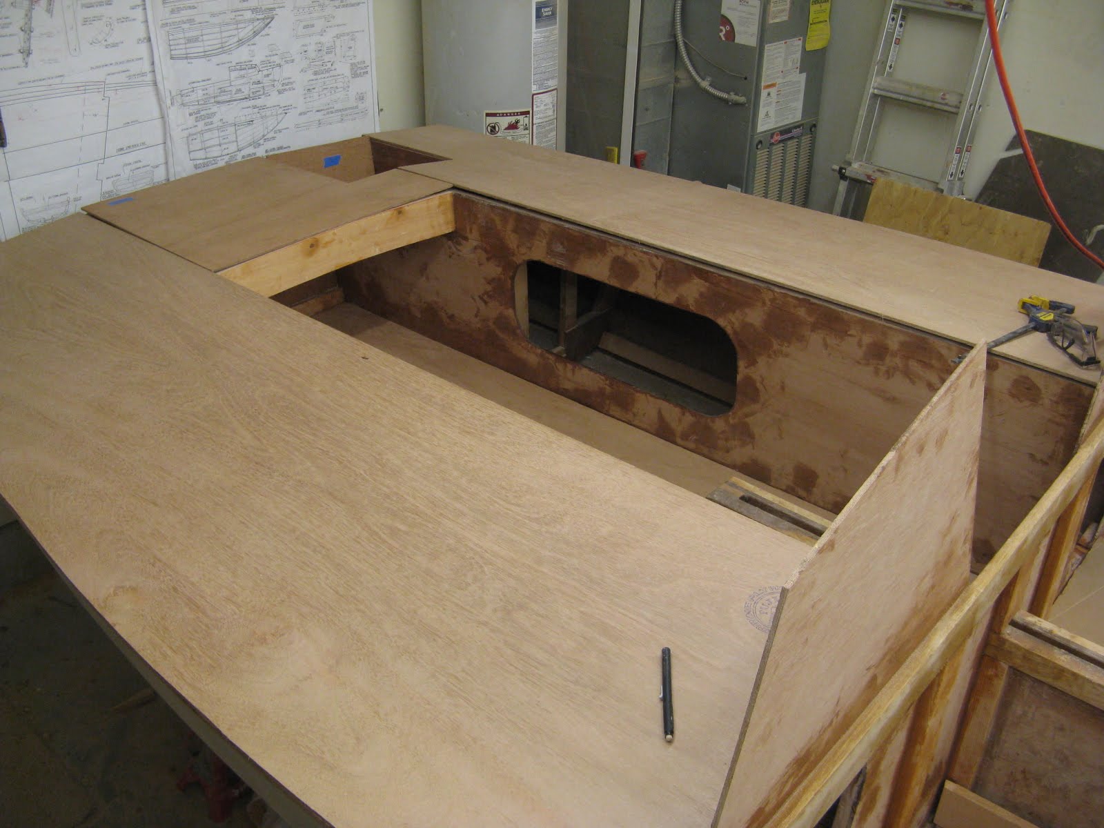
And now the last large pieces of plywood are cutout ... the cabin deck. Since these are the last large pieces of plywood going on the boat, I'll go through the whole detailed process of installing them one more time.

First the boat is used as a pattern. The plywood is clamped in position and the shape of the cutout piece is traced onto the plywood.


The pieces are cutout a little larger than necessary, just to make sure they aren't too short after they are bent into position. Then each frame is traced onto the plywood pieces.


Using the traced outlines of the frames as guides, pilot holes for the nails are drilled. This almost guarantees there will be no misplaced nails that miss the frames.

All surfaces are coated with straight epoxy, followed by a generous smearing of thickened epoxy.

The cabin deck is fastened at the centerline with a row of temporary screws (to be removed after the epoxy cures.) The plywood is bent over the frames and nailed into position. The nail heads are countersunk slightly into the surface of the plywood, then covered up in thickened epoxy.

All of the epoxy oozing out underneath needs to be cleaned up and filleted before it cures.


After the epoxy cures, the excess plywood is trimmed flush with the frames and cabin sides. I don't have pics of that, because I haven't done that yet.

Next I'm going to frame the companionway opening with some pieces of white oak.


Sunday, December 26, 2010

Cabin Frame

The frame for the windscreen and cabin deck (or roof?) is under construction. The windscreen and cabin deck are both cambered or curved, so all of the frame pieces have to be sawed out from larger pieces of lumber in a curved shape. The windscreen base is glued and screwed directly to the fore deck.

The cabin deck frame members are glued and screwed to the cabin carlines. The front frame member is a bit tricky, because it has to match the curve of the cabin deck and the curve of the windscreen. To accomplish this, the front frame member is cut out with a slightly larger curve than the others and installed at an angle. All of the frame members were roughly cut, then installed on the boat. Then they are trimmed to shape. So the lumber cutting didn't require a lot of precision and isn't as complicated as it looks.

After the frame members are installed, the top-centers of them are notched and a king plank of 1/4 inch plywood is installed. The king plank stiffens up the structure considerably.


The shape of the cabin is starting to become apparent.


The windscreen plywood is ready to be installed. Then, I'll finish the back part of the cabin frame, which will include a cutout for the companionway hatch.

I have some extra time to work on the boat during the holidays, so I'm hoping to get a lot done in the next week or so. I'll keep you posted.

Tuesday, November 2, 2010

Foredeck and Cabin Sides

The foredeck and side decks along the cabin have been installed. These are glued and nailed to the frame members.


The cabin sides have been made and installed. I modified the design to make the cabin sides and the cockpit coamings all one piece. I cut out a cardboard pattern first to avoid mistakes, then cut out the plywood. This helped me get the bottom curve right.

The pic below shows the cabin carlines being glued and nailed to the cabin sides. You can see some scrap pieces of 2x4 that have been cut to a curve and clamped to the assembly. This will make the curve of the top of the cabin side is the same as the bottom.

Here are the cabin sides all glued and nailed to the boat. I checked the angles to make sure everything looked right before the glue dried. One side was at a different angle than the other, so some ropes and clamps were added to hold everything in the right spot while the glue dried.

These window openings will later be sealed water-tight with acrylic windows.

Here's a better pic of the scrap 2x4 pieces that will later be removed. If you look close, you can also see a small slot in the side deck. This will be for a metal strap called a chainplate to pass through. The chainplate is where the standing rigging wire attaches to the hull. (more on that when I install the chainplates).


The next step is to install the frame members of the cabin roof and then install the cabin roof and cabin front. This will be a very similar process to the foredeck construction.

Saturday, September 11, 2010

Side and Aft Decks Glued and Nailed

The boat spent some time on the front lawn this weekend so I could pick up some plywood with the trailer. All the granny knots made when tying down the plywood reminds me that I need to learn how to tie knots before I go sailing for the first time. But I got the plywood home without it flying off and the trailer works great, besides being a bit bouncy without a boat on it.


The aft and side decks have been glued and nailed down. Before I glued the side decks on, I attached some pieces of Doug Fir to decks (nailing from underneath). These are the bases for the coamings. As you can see, the coamings are going to be curved nicely.

The holes in transom are also shown in the pic above. The top hole is a drainage hole for the motor well. The middle two are drainage holes for the cockpit. These holes may or may not be above the waterline, so I may need to plug them when sailing ... we'll see. The lower holes are drainage holes for the bilge, which will be plugged when the boat is in the water.

The boat is now safely in the garage again. In the photo below, you can see some notches in the coaming base pieces. This is for drainage, so water will not pool on the side decks along the coamings.

Here's a closer shot of the motor well. Just a watertight plywood box. The bottom is sloped toward the drainage hole. I still need to put a little oak cap along the back edge and round the edges a little.

I also glued and nailed the cockpit sole (floor). I cut some round holes in the floor for access to the back section of the bilge. These holes will be fitted with plastic watertight hatch covers.

Sunday, August 8, 2010

Cabin Bunks and Cutting Out Plywood

The frames for the cabin bunks have been made. Here is the fore-side of the bulkhead with some frame members added. I made the top piece out of white oak, since I figured I'd be kicking it a lot climbing in and out of the cabin.


All of the bunk frame pieces are screwed and/or glued into notches in the hull frames. They will strengthen up the structure of the hull as well as provide a flat surface to sleep on in the coffin-sized cabin. I still need to add a few more pieces around the centerplate trunk. I'm going to wait to do that until after the cabin framing is done and I'm ready to install the mast compression posts.


The bunk plywood is a strange shape that is impossible to measure without a pattern. This is my pattern made from scrap cardboard.


And here are the resulting bunk plywood pieces made using the cardboard pattern. The two plywood pieces are slightly different, since the boat isn't perfectly symmetrical. Good thing I checked that before I cut out both of them. This plywood is going to be removable (not glued down), since I want to be able to check the area underneath for debris or rot and also use that space for storage or flotation foam.


Also, there are some removable plywood floors inside the cabin on either side of the centerplate trunk.


I was curious if I had enough plywood, so I cut out a lot of the plywood pieces I will be needing later. Here are all the rudder pieces cutout and waiting to be glued together. The rudder is a hinging "kick-up" type.


Also I cut out the aft, side, and fore deck pieces as well as the cockpit sole (floor). All of these pieces will eventually be glued and nailed down, but they are not attached to the hull yet in these pictures. Yes, even the cockpit sole will be glued down, but with a few round waterproof access ports to inspect the bilge underneath. (Remember, I'm modifying the design to make a water-tight cockpit).


Finally I got a lucky break ... the side deck plywood pieces were JUST narrow enough to loft onto one sheet of plywood, creating very little waste. I didn't plan for that when modifying the design and widening them, but fortunately I didn't make them a half an inch wider.

Also, I faired the tops of all the deck frames to the proper camber, as you can kinda see in this pic.


I figure I need two more sheets of plywood to finish the deck and make the cabin. That purchase can wait a week or two though. Next I'm going to clean up, sand, and paint the bilge, since that will be easier to do before the decks are installed. This doesn't seem like the most fun task of boat building, but it's gotta be done.

Tuesday, July 6, 2010

Cockpit Framing

Well, it has been a year since I've started building the boat. A more ambitious or experienced builder may have been almost done by now. I'm working on the boat casually after work and on weekends. In the beginning, I often spent more time scratching my head looking at the plans than actually constructing something. And I took about two months off. Also, I'm trying to do everything myself, including rigging and sail assembly, which takes some extra time. Anyway, the boat is now over-budget and behind schedule ... not surprising for a project run by an engineer!

I made some good progress over the holiday weekend. The cockpit framing is almost done. There is nothing particularly difficult with this process ... just cut to length and make notches in the frames where necessary, then glue and screw.


All of this framing is going to be covered with a plywood deck. Well, everything except for the motor well, which is the small square opening (the far one with plywood sides, near the transom) in the picture below.


I had to modify the side deck frames to make the side decks (which are also where you are supposed to sit) wider, since I didn't notice how narrow the seats were until we flipped the boat over. These modifications weren't as difficult as I feared, but in hindsight I should have made this change in the beginning. I also installed a small stringer down the middle of the seats, so the side decks won't flex when I sit or stand on them.


I decided to cover the sides of the the foot well with plywood to make a water-tight cockpit, which isn't in the original plans. There are hatch openings in this plywood to access the storage areas under the side decks. I plan to make some water-tight plywood hatches to cover these openings. So any water flooding into the cockpit won't get into the bilge or cabin.


I also made some cutouts in the bulkhead to access the area under the side decks from inside the cabin ... and for better airflow inside the boat, which helps prevent wood rot.


I'm changing the design of the motor well too. I want some sort of motor well, since without one, an expensive bracket would be required to attach an outboard motor. (I can't afford a motor at the moment and I'm not sure if I will ever get one, but I'm building a motor well just in case.) Instead of the large motor well shown in the plans, I'm making a much smaller one off to the port side. Since I made the foot well so narrow, the motor well framing must be a little more complicated. I'm kinda just making it up as I go and it's all fitting together ok. (The following picture is looking down on the motor well framing. The plywood bottom of the motor well isn't installed yet.)


It all looks a little sloppily constructed, but the tops of all of these frames will later be planed fair and shaped so that the plywood decks will fit up nicely.